152 Support Insulator
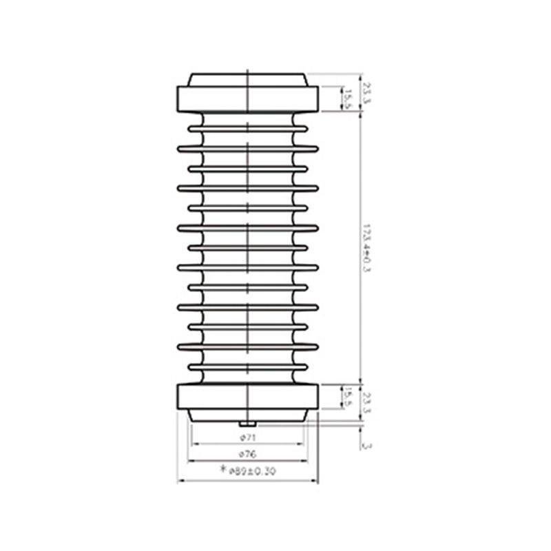
The 152 support insulator provides internal insulating support, with mounting faces, threaded inserts, actual height and mechanical loads checked for the application.
Support insulators provide insulating support and positioning for busbars or equipment parts. Selection combines mechanical loading, mounting connections and insulation layout. Appearance or a model number alone cannot establish suitability for a particular support arrangement.
The 152 support insulator provides internal insulating support, with mounting faces, threaded inserts, actual height and mechanical loads checked for the application.
The 192 support insulator serves equipment support and insulation arrangements, with end connections, load direction and electrical clearances assessed together.
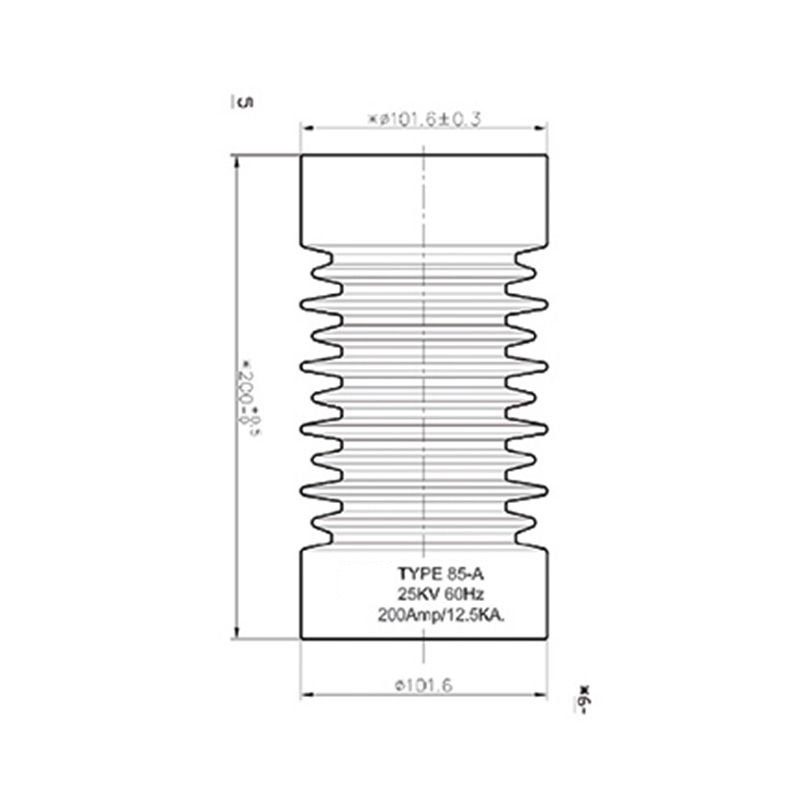
The 200 support insulator supports an insulated arrangement of conductive equipment parts, with end connections and mechanical loading checked for the application.
An insulating support for busbar or internal equipment arrangements, selected by installed height, threads, creepage and mechanical loading.
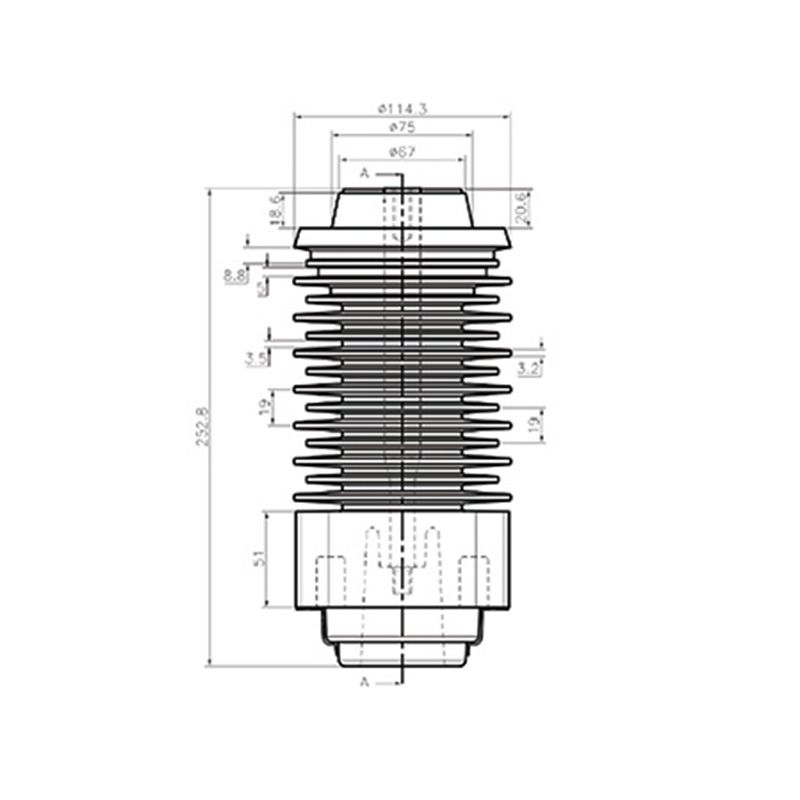
The 252 support insulator provides internal insulating support, with its mounting connections and mechanical duty selected from the specific product drawing.
Busbar orientation, connections and support spacing affect loading. Describe load directions and equipment layout so bending, tensile or compressive requirements can be assessed against the installation. A load value without direction and mounting context is insufficient.
Height, creepage path and air clearance are separate considerations. Model numbers do not replace dimensioned drawings, and a longer outline does not automatically establish suitability for pollution or outdoor exposure. Assess environment and insulation requirements with the specific construction.
A purely insulating support does not independently carry current. Define the insulating body, metal inserts and fixing hardware supplied. If an assembly includes a conductive path, identify its conductor and connections separately before assessing current requirements.
Also check threads, mounting faces, mechanical loads and insulation layout. Height is only one matching condition.
Select a purely supporting part by mechanical and insulation requirements. For a conductive assembly, assign current requirements to the identified conductive components.
Provide the support layout and end-connection drawings, load directions, insulation space, environment and required fixing hardware.