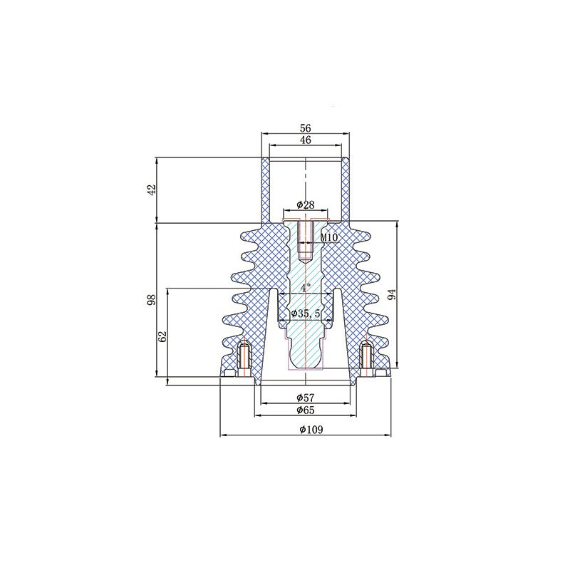
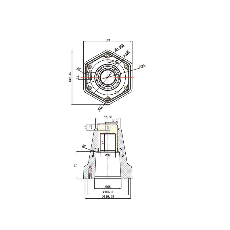
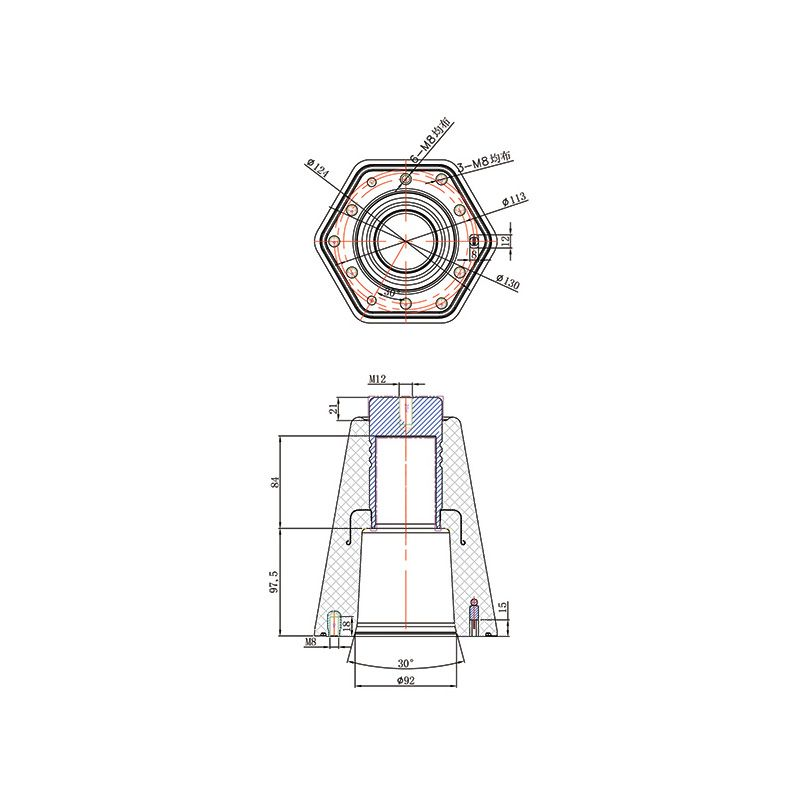
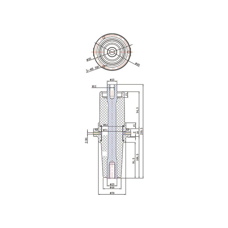
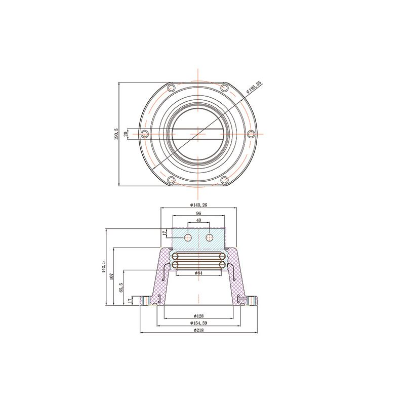
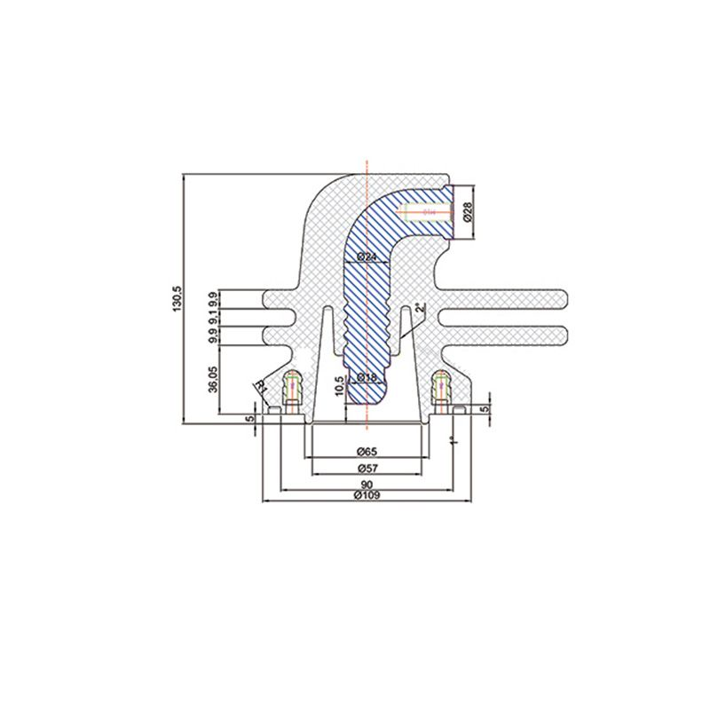
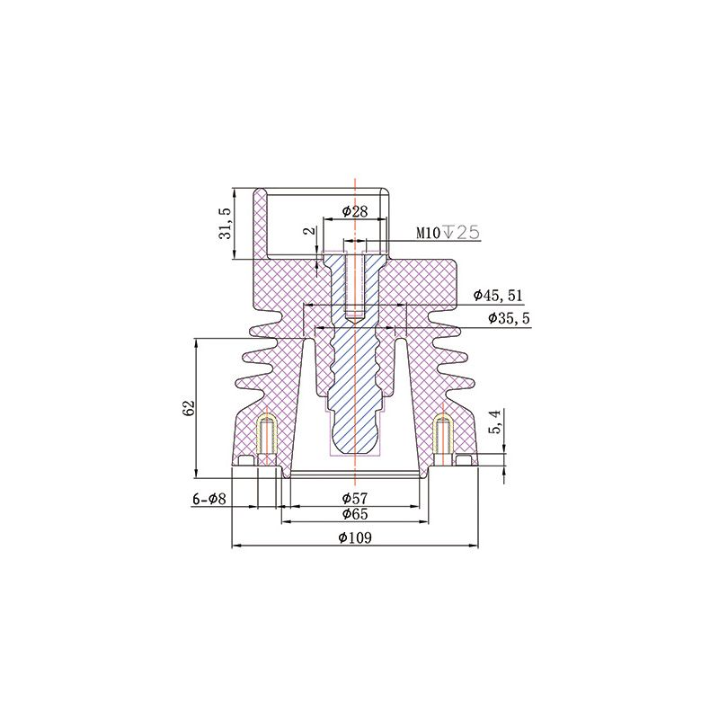
162 Bushing
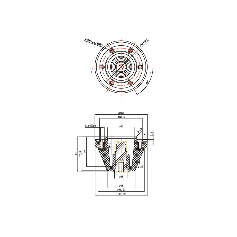
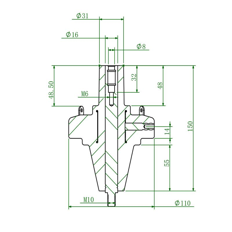
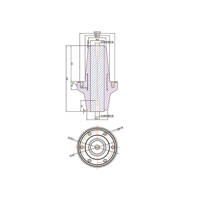
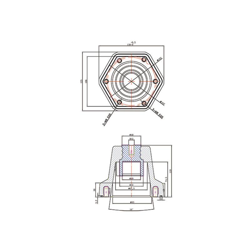
The 162 bushing provides an insulated through-connection, with end contacts, mounting geometry and insulation interfaces matched to the equipment.
Bushings provide insulated conductor connections through equipment boundaries; busbar sockets work with mating conductive connectors. Begin by identifying inner-cone, outer-cone, through-wall or side-extension arrangements, then assess the mating geometry, conductor construction and installation conditions.
The 162 bushing provides an insulated through-connection, with end contacts, mounting geometry and insulation interfaces matched to the equipment.
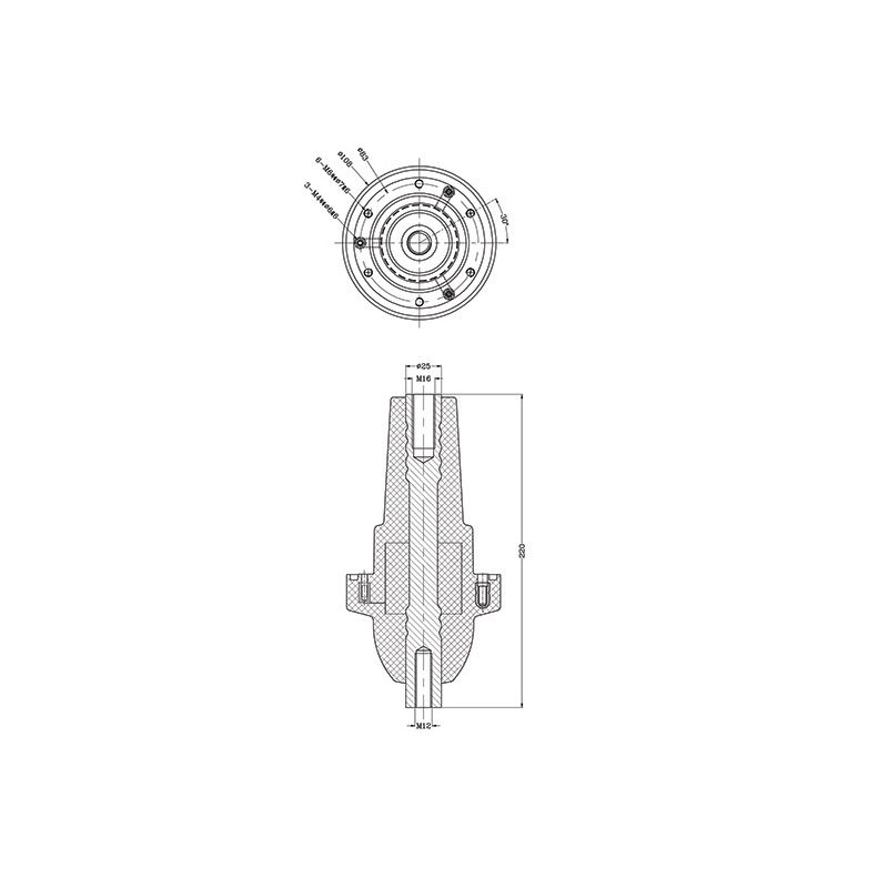
The 220 bushing serves an insulated conductor connection through an equipment boundary and must be distinguished from the 220 support insulator.
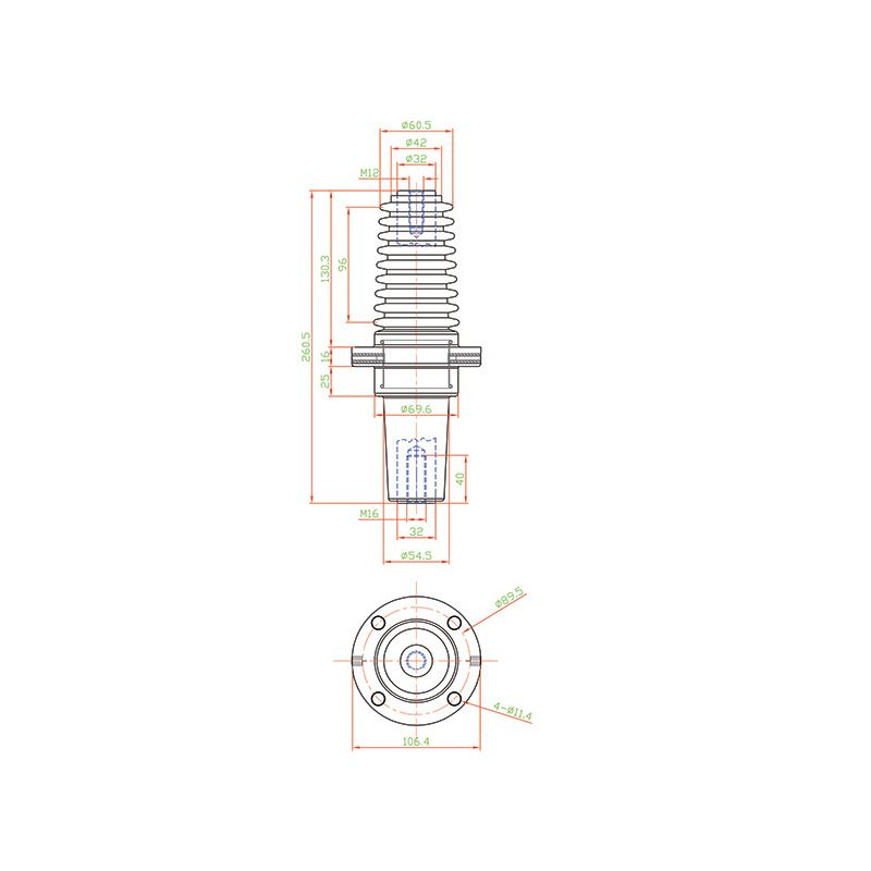
The 260 bushing provides an insulated conductor interface through a partition, with flange, terminal and mating geometry requiring coordinated selection.
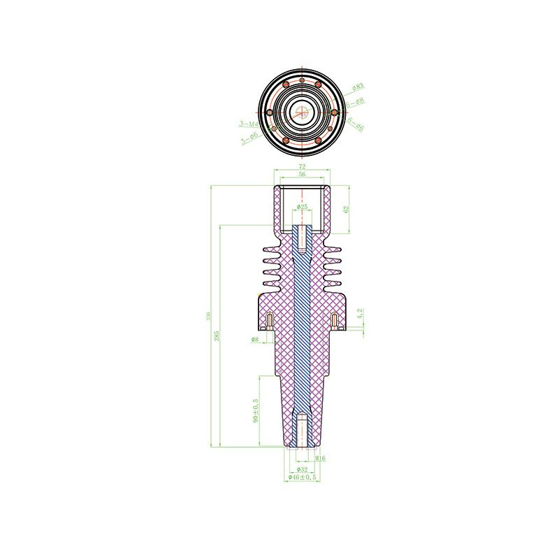
A bushing family for incoming and outgoing connections, with the 260 and 285 variants requiring separate terminal, mounting and conductor identification.
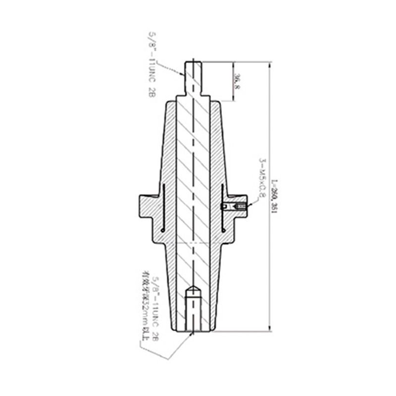
The 361/260 bushing provides an insulated through-connection, with end threads, the conductor and mounting faces matched to the equipment.
An insulated socket for a matched busbar connection, selected by contact geometry, insertion depth, retention and equipment layout.
An equipment bushing for insulated conductor connections, requiring confirmation of the insulation construction and service medium before matching terminals and seals.
The F-type bushing provides an insulated conductor connection, with end interfaces, flange dimensions and mounting orientation matched to the equipment.
An inner-cone bushing for a matched equipment connection, requiring identification of its drawing and mating conductor interface before selection.
An inner-cone bushing for switchgear connections, identified by installed height, flange arrangement and conductor layout.
The No. 2 inner-cone bushing provides a mating cone interface, with its designation, connector and retention arrangement requiring drawing-based confirmation.
The No. 3 inner-cone bushing requires its own cone, contact-depth and mounting checks rather than selection by reference to the No. 2 version.
An equipment bushing with an outer-cone interface, requiring a matched connector, contact arrangement and mounting flange.
A bushing for side-extension connections between switchgear sections, with inter-panel geometry, busbar connections and equipment ratings requiring separate confirmation.
An inner-cone bushing with a special connection layout, intended for selection against a specified enclosure space and connection direction.
The Type II inner-cone bushing has a distinct mounting and conductor layout that must be checked against its mating interface and enclosure.
An insulated conductor connection through an equipment partition, selected by the panel opening, flange fit, connections and clearances on both sides.
Cone interfaces require a matched connector; wall bushings require a suitable panel opening and space on both sides. Side-extension connections also depend on inter-panel busbar layout. These are electrical insulation interfaces, distinct from bronze bushings used for mechanical support.
A shared voltage class or similar designation does not establish interchangeability. Check cone dimensions and tolerances, contact depth, retention, threads and flange holes together. Numbers in a model name do not independently establish a dimension or standardized interface class.
Some enquiries concern an insulating body; others require an assembly with a conductor, contacts and seals. Current capability belongs to an identified conductive configuration and its connection and temperature-rise conditions. Confirm insulation construction and compatibility with the service medium separately.
Treat them as designations. Actual height and mounting dimensions come from drawings, and a similarly numbered support insulator is a different component.
Cone geometry, contacts and retention must all match. A shared product description alone is insufficient.
Provide the mating connector, interface drawings for both sides, mounting-panel details and service medium. Specify an insulating body or complete conductive assembly.