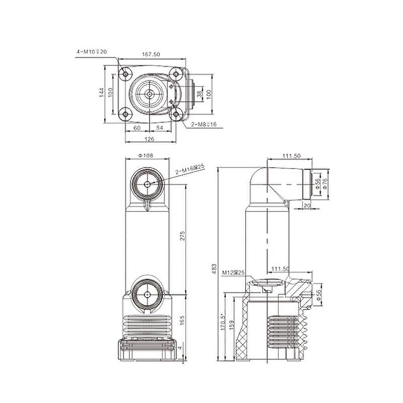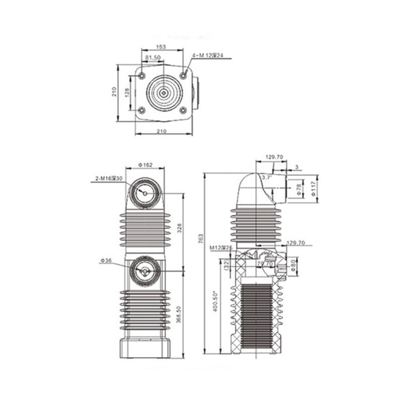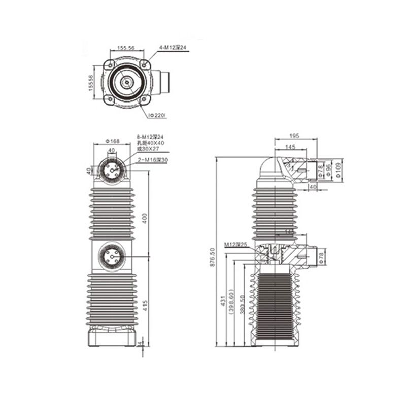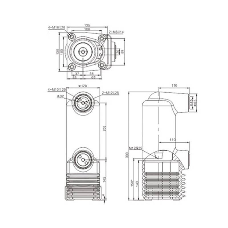
205 Embedded Pole
The 205 embedded pole combines a vacuum interruption component with pole insulation for circuit breaker assembly, subject to matching the interrupter and operating mechanism.
Embedded poles combine vacuum interruption components with external insulation for circuit breaker assembly. Selection brings together the interrupter, conductor connections and mechanical drive. A pole is part of an assembled breaker, so its configuration must match the intended switching duties and operating mechanism.
The 205 embedded pole combines a vacuum interruption component with pole insulation for circuit breaker assembly, subject to matching the interrupter and operating mechanism.
The 275 embedded pole is intended for vacuum circuit breaker assemblies, with conductor and drive interfaces that require their own matching drawings.
An embedded pole for vacuum circuit breaker assembly, with conductor construction, mounting datums and drive interfaces matched to the selected configuration.
An embedded pole for vacuum circuit breaker assembly, selected by terminal construction, installation space, thermal conditions and mechanism compatibility.
Similar pole outlines can contain different internal configurations. Identify the interrupter and mechanism output before checking travel, overtravel, contact force and mounting datums. Replacement selection must account for the complete operating interface, not just the visible shape.
Terminal orientation, connection faces and external busbars affect the assembly. Each current configuration needs an identified conductor and connection arrangement. Insulation, partial-discharge and temperature-rise information should apply to that version and its installation conditions.
List pole assemblies, connection pieces, fasteners and operating mechanisms separately. A complete-breaker enquiry also requires secondary controls and defined interruption duties. Documentation for a pole alone does not establish the performance of the complete breaker assembly.
Not by themselves. Use the dimensioned drawing for the relevant version to establish height, fixing centres and terminal locations.
Specify the pole and mechanism separately in the supply schedule and check their travel and output requirements together.
Provide the interrupter reference, pole and mechanism interface drawings, current and interruption requirements, required connection parts and quantities.